


")


Waveform input channels are buffered through amplifiers. If the programmable-gain option is fitted, the gains are individually software-settable to unity, x2, x5 or x10. Channels are then steered into the ADC (Analogue to Digital Converter) via multiplexers. The ADC converts an input voltage to a 16-bit digital value in approximately 0.5microSec and changing channels takes another 0.5, so the maximum single channel speed is 2MHz, which reduces to 1MHz for multi-channel capture. Sampling is inherently sequential; two channels cannot be sampled simultaneously.


Waveform channels
ADC LEDs
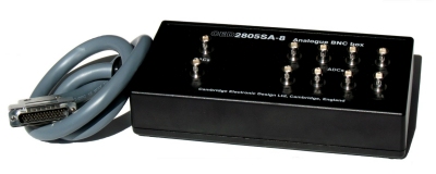
There are 16 waveform input channels on a standard Power1401. Eight channels are available through front-panel BNC connectors, labelled ADC Inputs, and eight through the rear-panel Analogue Expansion D-socket. Break-out boxes are available to convert these inputs to BNCs. The normal working input range of all of these channels is ±5 Volts or ±10 Volts, software selectable.
The front-panel waveform input channels each have an associated yellow LED. They are controlled purely by software command and turn on when the channel is in use.
Trigger
Trigger LED
There is a front-panel input labelled Trigger. This can be set by software to be the external signal to start the ADC converting. The ADC external convert input is also permanently wired through pin 6 of the rear panel Events D-socket. Conversions are usually initiated by a high-to-low transition. External convert signals are used when the conversion time is determined by an external event, e.g. when synchronising conversions to the phases of a rotating machine. When operating in internally-triggered mode the ADC typically samples at a fixed rate set by one of the clocks.
The trigger-input LED flashes on detection of an active-edge transition at the Trigger input. The LED can be set by software to be either on or off during its quiescent state.
Technical details: Analogue input
Trigger input
The input impedance of the waveform channels is typically 1 MOhm. The waveform inputs expect to be driven from a low-impedance source (100 Ohms or less); the output of most amplifiers is suitable. The maximum non-destructive input voltage range is ±15V. If you do overdrive the inputs, it is possible to damage the input buffer amplifiers.
The system accuracy and noise are 0.05% of full scale, ±1.5 bits.
The ADC
The input voltage is resolved into 65536 levels (16-bit precision); each step is approximately 150microV. Out-of-range voltages can cause incorrect output values and should be avoided. There is an option of programmable gain, x1, x2, x5, x10 on the 8 waveform inputs.
The front-panel Trigger input has in-line over-voltage protection and can accept signals in a ±40V range (absolute maximum). This input is held internally to +5V by a 100 kOhm resistor and has input hysteresis: the low-going threshold voltage is set at 0.95V and the high-going threshold at 1.2V. To pull this input low, the driving device must be able to sink 50microA. Pulses driving the trigger input should be 1microSec or longer.
The rear-panel ADC external-convert input responds to TTL and switch closure signals, and is held internally at +5V via a 10 kOhm resistor. Input pulses should not be narrower than 1µs and must fall below 0.8V for guaranteed recognition. This input is protected by a 100 Ohm series resistor and diode clamps to +5V and ground; the safe range is 0 to 5V. Conversion is normally initiated on the high-to-low edge. Use of the other edge can be selected by switches.
There are 4 waveform output channels on the Power1401. Two are available through BNC connectors on the front panel, labelled DAC Outputs (Digital to Analogue Converters), and two through the rear-panel Analogue Expansion D-socket. Break-out boxes are available to convert these outputs to BNCs.
The DAC waveform outputs produce voltages in the range ±5 Volts, in steps of approximately 150 µV, or 300 µV on the ±10V range.

The DACs can be set by program to update in response to an external signal, either the rear panel Event Clock F input or the front panel Trigger input, to synchronise the update rate to external equipment. When multiple channels of waveform are output, the Power1401 can be programmed to update several DACs simultaneously. The maximum update rate is 400kHz.
DAC LEDs
The front-panel waveform output channels each have an associated yellow LED. The LED turns on when the channel is in use.
Technical details
The waveform outputs are designed for driving loads of 600 Ohms or higher impedance and are short-circuit proof. For full accuracy, the load should not be less than 5 kOhms.
© Copyright CED 2024
Registered in England: 00972132
Registered office:
- Cambridge Electronic Design Limited,
- Technical Centre,
- 139 Cambridge Road,
- Milton,
- Cambridge CB24 6AZ
- ENGLAND.
VAT: GB 214 2617 96
Producer registration number: WEE/BD0050TZ
For our US customers, we can provide tax form W-8BEN, that identifies us as a UK company.
CAGE/NCAGE: KB797
NAICS: 423490
Hardware: 84716070
Software: 85235190
By email:
By post:
- Cambridge Electronic Design Limited,
- Technical Centre,
- 139 Cambridge Road,
- Milton,
- Cambridge CB24 6AZ
- ENGLAND.
By telephone:
(Int.+44) (0)1223 420186
From North America (Toll Free):
1 800 345 7794