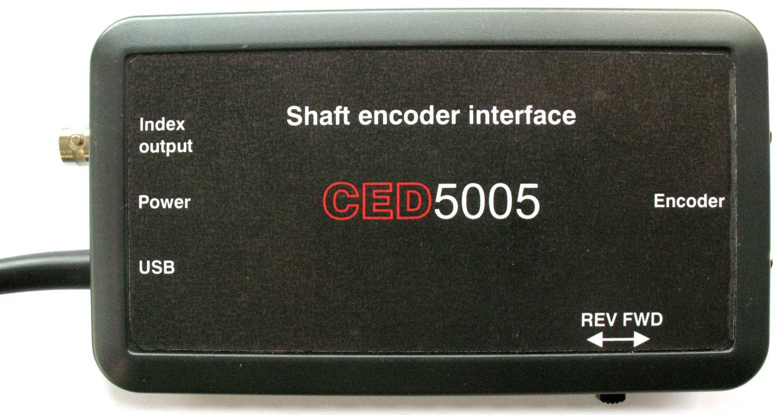
CED 5005 Shaft encoder
The CED5005 Shaft Encoder Interface connects the output of a standard quadrature shaft encoder to a PC USB port. All operational functions of the interface are set under program control via the USB port.
The CED5005 supplies 5V power to the shaft encoder, and expects to receive TTL-compatible A and B quadrature signals and a positive-true TTL index signal. The quadrature signals control an up-down counter that holds a value representing the shaft angle. The counter is reset to zero each time it receives the index signal. This arrangement is independent of the counts per revolution, which is determined by the shaft encoder. A 360ppr encoder gives counts in degrees.
A hardware-generated TTL index output from the CED5005 becomes active when the rotating shaft passes through a program-specified angle relative to the index. This index output can be used to generate a reference marker for peri-trigger data acquisition systems.
The interface box has a slide switch that interchanges the A and B quadrature signals going to the decoder. This has the same effect as reversing direction of the shaft, so can be used to define which direction of physical rotation causes an increasing rotation count in the interface.
Main functions
The CED5005 operates using SPI protocol running at a nominal 1MHz bit rate. It permits reading of the shaft rotational angle at any time, but at high shaft rotational rates the SPI reported angle can lag the actual shaft angle due to the delay time in the SPI data transfers.
The CED5005 generates a flag (index) pulse when the encoder output passes through a program-specified angle relative to the encoder's index point. This flag output is not subject to any SPI delay. Instead of simply an angle comparison output, the flag signal can be programmed to be any combination of the angle comparator, the index, the counter carry (in a forward direction) or the counter borrow (when reversing).
Although the encoder is expected to be mounted so that, under normal “forward” rotation, its outputs have the A signal leading the B signal, the interface correctly tracks reverse motion, where B leads A. The switch on the encoder case allows the user to set which is the nominal forward and reverse direction.
Power on zeroing
After initial power-up and program load of the operating configuration, it is necessary to ensure that, before operational use, there is at least one whole shaft revolution in the nominal forward direction in order that the index pulse can be guaranteed to zero the angle counter.
Encoder connector
The following table gives the encoder connections on the 9-pin D socket:
| Signal | Pin | Comment |
| Channel A | 4 | 5V TTL |
| Channel B | 3 | 5V TTL |
| Index | 2 | 5V TTL |
| +5 Power | 5 | From USB |
| Ground | 1, 9 |
Additional documentation
The CED5005 uses an FTDI C232HM USB-SPI adaptor, which houses an FT232H device in the USB plug of the interface. This adaptor is a generalised controller unit configured for SPI operation through a Windows driver and a C program library.
The CED5005 encoder interface uses an LSI LS7366R quadrature counter to track the quadrature signals from the shaft encoder. It connects via SPI to the USB-SPI adaptor, and has several control registers that need to be set up for the intended mode of operation. Links to the relevant FTDI documentation and the LSI/CSI LS7366R data sheet are given at the end of this section.
The CED5005 is supplied with the source of a simple C++ program to demonstrate basic operation. The demonstration program is expected to be run using Microsoft Visual Studio, which available as a free download from the Microsoft web site.

£550
Only in English
Registrado en Inglaterra: 00972132
Oficina registrada:
- Cambridge Electronic Design Limited,
- Technical Centre,
- 139 Cambridge Road,
- Milton,
- Cambridge CB24 6AZ
- ENGLAND.
VAT: GB 214 2617 96
Número de registro de productor: WEE/BD0050TZ
Términos y condiciones de venta
Para nuestros clientes estadounidenses, podemos proporcionar el formulario de impuestos W-8BEN, que nos identifica como una empresa del Reino Unido.
UEI : EQ4LMQ1M2ZS5
CAGE/NCAGE: KB797
NAICS: 423490
Hardware: 84716070
Software: 85235190
Por email:
Por correo:
- Cambridge Electronic Design Limited,
- Technical Centre,
- 139 Cambridge Road,
- Milton,
- Cambridge CB24 6AZ
- ENGLAND.
Por teléfono:
(Int.+44) (0)1223 420186
Desde Norteamérica:
1 800 345 7794


