


CED 3505B Programmable attenuator with differential I/O
Overview
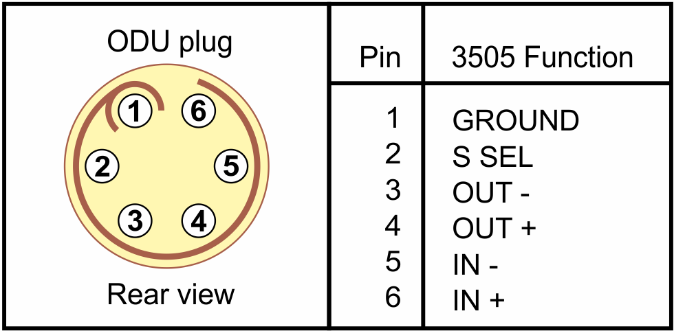
The 3505B incorporates differential I/O circuitry designed to maximise the signal-to-noise ratio at the attenuator output. This is particularly useful when using higher attenuation settings, giving an improvement in signal-to-noise ratio at the output of around 30dB compared with the front-panel BNC output. The differential I/O signals are available on a 6-pin ODU socket mounted on the 3505B front panel in place of the pulse out BNC or the headphone jack.
The 3505B price includes a 1m dual ODU plug cable that has BNC input and output connectors for interface to standard single-ended equipment. Also included is an un-wired ODU plug for the user to wire as required.
In addition, we offer a selection of I/O cabling for sale for use with both differential and single-ended user signals. The list includes a break-out box fitted with 3.5mm jack sockets that connect with standard 3.5mm TRS or TS leads. Cables are also available for daisy-chaining of 3505B attenuators using differential signalling. Connecting two or more attenuators in series that have a higher and a lower attenuation step size is a way of allowing fine resolution of attenuation changes in a large overall range of attenuations.
Signal routing
With the 3505B option, the attenuator output is permanently available both in single-ended form on the standard front panel BNC output connector and as a differential pair on the ODU connector.
The 3505B attenuator input is dynamically selectable to be taken from either the standard front-panel BNC input or the ODU input socket, the selection being determined by wiring on a selector pin on the ODU connector. If the pin is open circuit, the front-panel BNC input is used; if the pin is grounded, the ODU input is used. In this way, an ODU plug can be wired to work with either or both of input and output cables, or with an external switch closure to select the input to use. The break-out box mentioned in the overview above automatically switches whenever an input cable is plugged into the box.
I/O signal levels
To achieve maximal signal-to-noise ratio and to minimise the effect of external interference, balanced differential signals are twice the amplitude (as measured between signal+ and signal-) of an equivalent single-ended signal.
The design of the differential I/O circuitry on the 3505B is such that the -ve signal can be grounded on either or both of the input and output differential pairs so that the attenuator can be used with cabled single-ended connectors such as BNC plugs.
At the differential input, grounding the -ve pin of the input pair gives the expected simple divide-by-two on the +ve input signal, since the antiphase signal is zero.
At the differential output, the circuit is arranged so that, if the -ve output is grounded, the +ve output carries the whole differential signal at an amplitude that is twice that of the single-ended front-panel BNC output. Because of the matching ratios of two at the ODU input and output, use of BNC cabling from the ODU connector for both input and output gives 0dB gain or loss. However, using the BNC front-panel input in conjunction with ODU-cabled BNC output would give a 6dB increase in the output signal level. This should be borne in mind when planning laboratory configurations.

Daisy-chain cable showing series-connection of 3505B attenuators

The break-out box provides TRS sockets
Specifications
The differential option in the 3505B does not change the specification of the attenuator when it is used through the front-panel BNC inputs and outputs. When the differential inputs and outputs are used, the following characteristics apply (typical values given unless otherwise stated):
| Input voltage maximum (differential) | ±20V peak (+25dBu, 14V r.m.s.) | |
| Input voltage maximum (single-ended) | ±10V peak (+19dBu, 7V r.m.s.) | |
| Input impedance (differential) | 24 KOhm | |
| Input impedance (common-mode) | 18 KOhm | |
| Input common-mode rejection | 90 dB | |
| Input offset voltage (differential) | ±10 μV | |
| Output voltage maximum (differential) | ±20V peak (+25dBu, 14V r.m.s.) | |
| Output voltage maximum (single-ended) | ±10V peak (+19dBu, 7V r.m.s.) | |
| Output impedance | 50 Ohm | |
| Output signal balance | 54 dB | |
| Output offset voltage (differential) | ±10 μV | |
| Output offset voltage (common-mode) | ±50 mV | |
| Output short-circuit current | ±85 mA |
5. Output signal-to-noise ratio (SNR) in dB 20Hz – 20KHz
| Configuration A: | fully differential I/O via ODU connector |
| Configuration B: | single-ended BNC I/O via ODU connector |
| Configuration C: | front-panel BNC input, ODU differential output |
| Configuration D: | front-panel BNC I/O |
Measurements taken on a 3505 attenuator with 3dB steps. SNR figures given are the ratio of in-band r.m.s. output voltages with input signal applied to the same with input grounded. The configuration C figures are corrected for the additional 6dB gain (see overview section, above).
| Configuration | A | B | C | D |
| Attenuation dB | SNR dB | SNR dB | SNR dB | SNR dB |
| 0 | 118 | 118 | 112 | 87 |
| 30 | 87 | 87 | 81 | 58 |
| 60 | 57 | 57 | 51 | 27 |
© Copyright CED 2026
Registered in England: 00972132
Registered office:
- Cambridge Electronic Design Limited,
- Technical Centre,
- 139 Cambridge Road,
- Milton,
- Cambridge CB24 6AZ
- ENGLAND.
VAT: GB 214 2617 96
Producer registration number: WEE/BD0050TZ
For our US customers, we can provide tax form W-8BEN, that identifies us as a UK company.
UEI : EQ4LMQ1M2ZS5
CAGE/NCAGE: KB797
NAICS: 423490
Hardware: 84716070
Software: 85235190
By email:
By post:
- Cambridge Electronic Design Limited,
- Technical Centre,
- 139 Cambridge Road,
- Milton,
- Cambridge CB24 6AZ
- ENGLAND.
By telephone:
(Int.+44) (0)1223 420186
From North America (Toll Free):
1 800 345 7794